Monday, November 14, 2011

Half a year in a roll of film

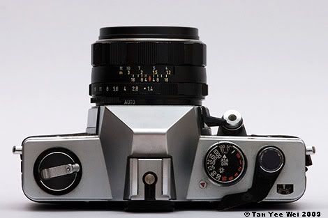
I have a film camera, a delightful little semi-automatic SLR with manual aperture and focus controls.


Click here for large size image


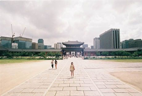
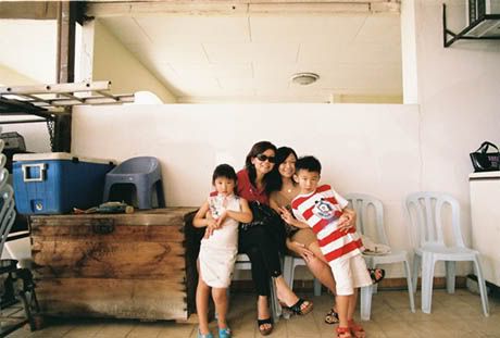
Every now and then, I will persuade myself that this function/ event I’m going to is going to be great and I should bring my camera… my FILM camera. But when I get there there’s not so much going on that justifies squeezing off a RM 0.65 shot so I usually end up with a photo or two, sometimes 5. The small number of photos and my boring social calendar means it takes about 6 months for a roll of film to be used, by then I’m a bit jaded by the hassle and lack of instant-ness of film.


Click here for large size image


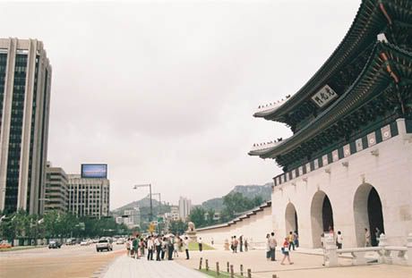
I get the roll developed and scanned, and immediately get stunned by the vividness of it. The dynamic range is fantastic – there simply are no blown-out areas, and the tonal gradients look rather pleasing.


Click here for large size image


It also helps with my composition that I take extra care to squeeze the trigger when RM 0.65 is on the line, so I end up with a higher proportion number of better photos.

I should... will take the film camera out more.

Labels: , ,

Thursday, May 13, 2010

The background story on how to imitate the Minolta/Sony Smooth Transition Focus bokeh on regular, large-aperture lenses

This is an investigation of a concept, not the actual building process. This article will involve more mathematics than you’d probably care to read.


Basis of the STF

The STF lens is an innovative lens by Minolta (and now marketed by Sony) that gives exceptionally smooth bokeh by using a piece of grey-coloured glass to regulate light fall-off of the bokeh.

Very simply, this works by making the circle of confusion’s (the bokeh) brightness gradually fade. This is in contrast to normal lenses where the circle of confusion is a very well defined circle (or hexagon/pentagon/octagon, if the aperture blades are slightly closed).

The results are very smeared circles of confusion, as illustrated by the comparison images below.
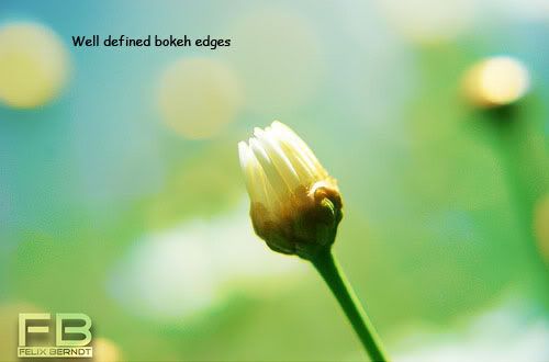

Photo using a regular, large aperture lens



Photo using an STF lens


The design and ingenuity behind the STF mechanism is described here, with lots of sample photos from the STF lens.


Existing imitation techniques

On Minolta Dynax 7 film cameras, the STF’s smooth bokeh can be mimicked by taking seven exposures on one frame, each exposure with a smaller aperture size. This results in circle of confusions with bright centres and progressively dimmer towards the edge.

Alternatively, a long exposure can be made in dim lighting with the camera mounted on a tripod. The aperture ring can then be manually turned to reduce the aperture over the entire duration of the exposure. For this approach, manual lenses with no aperture clicks are most suitable.


Proposed filter-based mimickery

Here, I propose using a lens filter to reproduce the light falloff that an STF lens’s coloured lens. If a filter can be darkened at the edges to allow a gradual light falloff, then the resulting bokeh will have a similar falloff characteristic. The falloff can be controlled by adjusting the darkness of the glass at different distances from the centre.
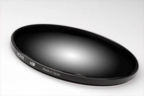

Proposed concept: radial gradient neutral density filter


This filter-based approach has been used to shape bokeh, resulting in heart, star, square shaped bokeh:
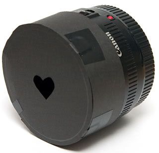

A heart-shaped bokeh filter
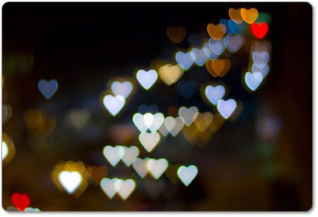


Result from a heart-shaped bokeh filter: circle of confusion (bokeh) partially obscured, resulting in heart shape


Light falloff modelling

Light falloff on the proposed radial ND filter can be done by attempting to mimic the STF lens’s material thickness and how it absorbs light.

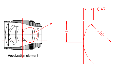
The first assumption would be to make an approximation of the filtering element’s lens shape. It is reasonable to assume that the lens is a spherical lens, since spherical lenses are generally much easier to cut than other aspherical shapes.

Based on schematics by Minolta (above), the lens’s geometry can be scaled to a common distance scale based on the lens’s radius:

Approximating the coloured glass's dimensions


Lens radius: 1.00r
Lens thickness at centre: ≈ 0
Lens thickness at edge: 0.47r
Sphere radius: 1.29r

After some geometric manipulation, the lens thickness can be expressed by the equation

which describes the lens thickness, t, at a particular radius, r.


To calculate the optical density of the glass, it’s useful to note that the aperture number of the Minolta STF lens is f/2.8, but the amount of light let in is equivalent to f/4.5 (the lens’s name is 135mm f2.8 [T4.50] STF). This can tell us that the coloured lens removes approximately 1.4 stops of light, from the following relation:
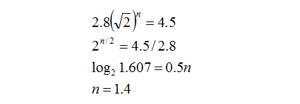

If by removing 1.4 stops of light, this means that only 0.51.4 (39%) of the incoming light passes through; the rest is absorbed by the coloured glass.


In order to select the correct optical density for the filter to match Minolta’s design, we need to match the total light transmitting through the filter to be similar to what Minolta has for the STF lens (39%).

Arbitrarily assuming that the edge of the lens removes p stops of light passing through (similar to the dynamic range of slide film), and using the knowledge that the glass thickness and optical density is proportional, the number of stops removed at a particular radius can be expressed as:
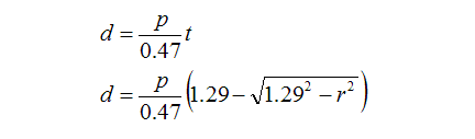
(0.47 is the thickness of the edge of the coloured lens)

This means that for light passing through any portion of the lens, the quantity that passes through can be expressed as 0.5d. To calculate the total amount of light passing through the entire lens, we need to add intensities of all the different rays of light coming through (some rays weakened due to passing through lots of dark glass, some rays not so weak due to passing through less glass).

The integral below does that:
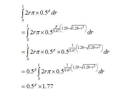

To find the value of p, the above equation needs to match the transmissivity of the Minolta’s coloured lens, which is 39%.
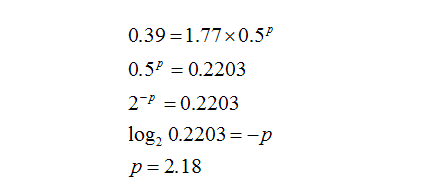

Therefore, the edge of the filter needs to absorb 2.18 stops of light, letting through 22%, while the centre practically lets everything through.
For the proposed filter to match the light falloff of the STF’s bokeh, the filter’s darkness needs to be the same as the STF’s coloured lens. Therefore, the same equation can be used to describe the filter’s darkness at all radiuses:
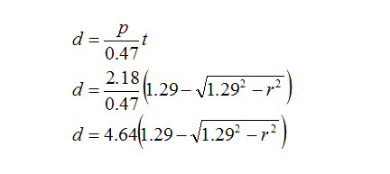

For this equation, the length scale is set such that the filter’s radius is 1.00.


Having obtained the proper light falloff characteristic and the relationship between optical density and radius for the filter, the filter can be constructed. This article will be continued as progress is made during construction.
Labels: , , ,

Monday, April 13, 2009

How to test/ calibrate a manual SLR camera's shutter using a digital camera

Abstract:

Before loading a newly acquired second hand camera with film, it is often a good idea to check if the shutter is working correctly. This is particularly true for well used, older cameras.

While slow shutter speeds with exposures greater than 1 second can be verified using a stopwatch, it becomes much harder to check for fast shutter speeds.

This document presents a technique to verify the accuracy of a manual camera’s shutter speed by using a digital camera as the standard shutter and the recording device.


Equipment set up:


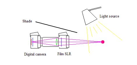
Figure 1: Shutter calibration equipment set up.
Red: digital sensor, blue: shutters, magenta: light rays, green: lens


1. The manual SLR’s lens is removed, and the film back opened to expose the shutter from both sides.

2. The digital camera is pushed as close to the manual SLR’s shutter as reasonably safe.
Caution: Ensure that nothing touches the shutter, as interrupting its movement will risk damage.
3. Arrange a subject beyond the manual SLR for the digital camera. Ideally, this subject should be of uniform colour and not throw bright reflections. The uniform colour will make brightness comparisons much easier.
Tip: Use a lens with a long focal length on the digital camera, and set it’s aperture to a small opening (5.6 or smaller). This will minimise vignetting caused by the SLR’s frame partially blocking the view of the digital camera.

4.Open the manual SLR’s shutter (using bulb mode or a long exposure), and focus the digital camera on the subject.

5. Illuminate the subject with a bright light source, and shade the digital camera from the light source. Ensure that minimal ambient light reaches the area between the digital camera and the manual SLR.


Set up notes:

When properly set up, the only light that reaches the digital camera’s sensor will be light from the illuminated subject. For the light to reach the digital camera’s sensor, it needs to pass through two shutters – the digital camera’s and the SLR cameras.

Light from the subject will reach the digital camera’s sensor if and only if both shutters are open.


Testing procedure:

6. With the manual SLR’s shutter open (using a long exposure), meter the scene and adjust the digital camera’s aperture and ISO so that the shutter speed matches the value to be tested.

7. With the SLR’s shutter open (using a long exposure or bulb mode), take a photo of the scene using the preset ISO, aperture and shutter speeds. This is the standard image, because the exposure time is that of the correct shutter speed. The SLR’s shutter was open throughout the experiment, and the exposure occurred only during the time the digital camera’s shutter was open.

8. Set the digital camera’s shutter speed to bulb (or a long exposure), retaining the same aperture and ISO settings in the previous step. Set the manual SLR’s shutter speed to the tested speed.

9. Open the digital camera’s shutter, then release the manual SLR’s shutter. Close the digital camera’s shutter (by releasing the shutter button if in bulb mode, or allowing it to close after the preset time). This is the tested image, because the exposure time is that of the tested camera’s shutter speed. The digital camera’s shutter was open throughout the experiment, and the exposure occurred only during the time the SLR’s shutter was open.


Comparing the results:

10. Both the calibrated and the tested images are opened, and their histograms observed.

11. Brightness peaks associated with the illuminated image are identified and their locations along the histogram compared.

If both shutters have identical exposure times, the peaks of both images would lie in the same locations.


Error estimation:

In the unfortunate event that the shutter speeds do not match, and the digital camera’s shutter speed is trusted, the error of the manual SLR’s shutter can be estimated.

12. Repeat step 7 using several exposure times.

13. Compare the images from the various exposure times with the tested image obtained from step 4. Find the closest match between the tested image and one of the standard images.

14. Calculate the manual SLR’s shutter error in terms of number of stops.

15. The error estimation needs to be repeated for every shutter speed available on the manual SLR to establish the real exposure that each shutter setting will give.

Labels: , ,

Saturday, April 11, 2009

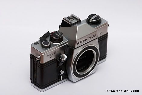
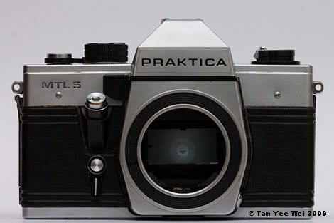
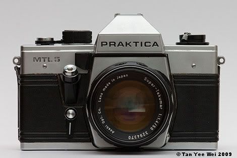
Camera porn – Praktica MTL 5

I got a new camera!

An M42 screw mount camera from the now defunct German Democratic Republic (in general, Democratic Republics are anything but democratic).

*orgasms*
*squirts*


*grins*


Click here for large size image


I have a bunch of screw-mount lenses for use of my DSLR, but I’ve always had this little itch for a fully mechanical screw mount camera body. There’s something particularly satisfying from turning knobs and aperture rings, cocking the shutter spring and releasing the shutter through a mechanical linkage.

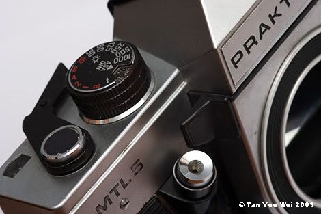
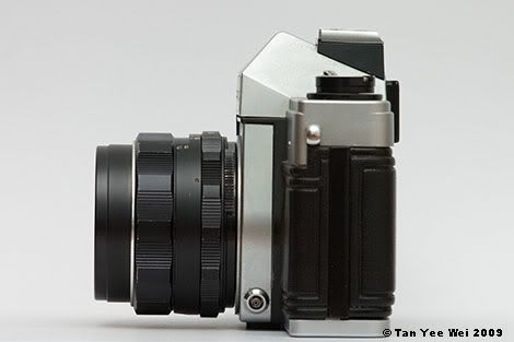
Praktica cameras have a little oddity – the shutter release button protrudes from the front instead of being mounted on top of the body.


Click here for large size image


Click here for large size image


Click here for large size image


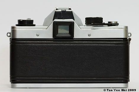
As with a basic film camera, there are only four fundamental controls: focus, aperture, shutter speed and shutter release. The back view comes across as shockingly minimalist – there is no window to show the film canister’s markings, neither is there a slot to put notes indicating the film type you have loaded. Not to mention the comforting absence of buttons and LCDs heh.


Click here for large size image


Click here for large size image


Click here for large size image


Now I have a new problem – my camera bag does not have enough space.

Labels: ,

Tuesday, July 29, 2008

Depth-of-field considerations when choosing between a full-frame and reduced-frame digital SLR

Introduction

Main considerations when comparing full-frame and reduced frame digital SLRs typically lie in the areas of price, image quality and view-angle.

One often neglected area comparison is the depth-of-field that each camera would give.

The comparison here would be based on APS-C and 35mm, and the basis of comparison will be prime lenses of commonly available focal lengths and apertures.

The prime lenses used are as follows:
20 mm f/4.5
24 mm f/3.5
28 mm f/3.5
35 mm f/2.0
50 mm f/1.4
85 mm f/1.8
108 mm f/2.8
135 mm f/3.5
200 mm f/4.0


Comparison methodology

After visualising a scene, a photographer must select the appropriate focal length to cover the correct view angle. This focal length is dependent of the sensor size used. The focal length on a full frame camera is 1.6 times that of a APS-C camera to result in the same view.

For example, a 50mm lens on an APS-C camera will give the same view angle as an 80mm lens on a full frame camera.

Using idealised equations (which are suitable for use with prime lenses due to their reasonably simple optical design), the depth of field can be calculated when the sensor size, focal length, aperture, and subject distance is known.

In this simulated study, the following is assumed:
The photographer wants to capture an object 3m wide on camera. After putting on a lens, the photographer moves himself to a position so that the 3m object fills the frame. He then selects the largest aperture, and then observes the depth of field after taking the photograph.


The following correlation is used:

Where N is the aperture number, f is the focal length, s is the distance to subject, and c is the circle of confusion diameter. This correlation is applicable for moderate to large distances. [source]

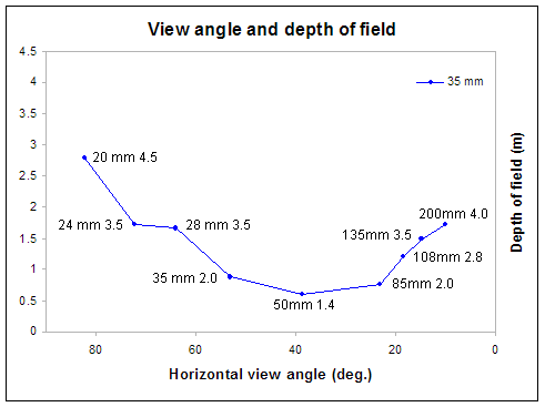
Using this correlation for a full frame camera and 50mm f/1.4 lens, we adjust the subject distance to 4.3 m so that the 3m wide subject fills the frame. We then determine the depth of field (in this case it is 0.6 m). A 50mm lens on a full frame camera spans a horizontal view angle of 39°.

The result can be charted on a graph, where we compare view angle with depth of field.


Figure 1. The depth of field of various lenses when mounted to a 35mm camera, with aperture wide open and the subject distance adjusted such that a 3m wide object fills the frame.


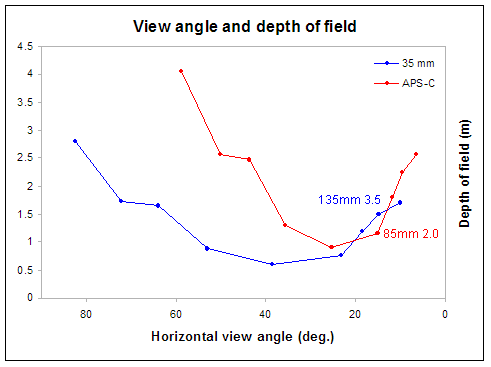
The same exercise is repeated for the APS-C camera, and the data is plotted on the same chart for comparison.

We see that the view angle for the lenses are narrower, which is not surprising since the APS-C sensor is smaller and thus sees a narrower field. A correlation between the view angles of full frame and reduced-frame cameras is as follows:

When mounted on a reduced frame camera, the view angle is the same as a lens 1.6 times longer mounted on a full frame camera. For example, the view of a 50mm lens on an APS-C camera is equivalent to that of a 80mm lens on a full frame camera.


Figure 2. The depth of field of various lenses when mounted to a 35mm camera and an APS-C camera, with aperture set to wide open and the subject distance adjusted such that a 3m wide object fills the frame.


More importantly, the depth of field becomes wider when using a reduced frame camera. This is the case through the entire range of lenses, except at 85mm, where an 85mm lens on a reduced frame will out-bokeh a 135 mm lens on a full frame camera. Incidentally, the view from these two set-ups are equivalent. A 85mm on APS-C looks like a 136mm on full frame (85 x 1.6 = 136).


Conclusion

Depth of field at any specific view angle is dependent on both the view angle and aperture size. Using a system of inter-changeable lenses on both full frame and reduced frame cameras, the full frame camera consistently results in a narrower depth of field, aiding the application of bokeh.

Labels: , ,

Saturday, October 20, 2007

Using DOF indicators on small-frame digital SLRs

Almost all manual focus lenses include a depth of field scale showing the region that would be in acceptable focus.

These DOF scales are designed for film cameras, and will give erroneous results when used with a small sensor.

To find out how to correct for this error in sensor size, it is necessary to look at the mechanism in which the depth of field is produced. The near and far limits of the region in focus are estimated by the following equations:


Where:
DN and DF are the near and far limits of the field of focus
f is the focal length of the lens
s is the distance to the subject
A is the aperture number
c is the radius of the circle of confusion.

The circle of confusion requires a bit of explaining:
If an image is in focus, a point on the subject is projected as a point on the sensor. But the image is out of focus, a point is projected as a circle of light on the sensor. If this circle of light is sufficiently large, then the image will be visibly out of focus. For everything that lies between DN and DF, the circle light projected onto the sensor is smaller than the circle of confusion, and so remains in acceptable focus.

The circle of confusion is directly proportional to the sensor size. Thus c can be written as kZ, where Z is the length of the sensor.


As the equation shows, changing Z from 36mm to 22.5mm (APS-C sensor size) will change the depth of field in a manner that cannot be estimated quickly. Another approach is taken.

Say that we have the subject, and the focal length is fixed. We also know the depth of field that we want. Thus everything in the above equations are already fixed with the exception of A (the aperture size) and Z (the sensor size).

Conveniently, A and Z only appear once in each equation. Even better, they are multiplied together with other terms.

Thus, if the depth of field, subject distance and focal length are fixed, the product AZ needs to be constant.

For 36mm film, a certain aperture (which we will call A1) will be used.
For a 22.5 mm sensor, a certain aperture (which we will call A2) will be used.

Recall that AZ needs to be constant, then:

36 x A1 = 22.5 x A2
A2 / A1 = 36 / 22.5
A2 = 1.55 x A1

To maintain the same depth of field as a 36mm film camera, the aperture on an APS-C camera needs to be 1.55 times the aperture on a 36mm camera.

And here comes the most useful approximation:
1.55 is very near to 1.414. This magic number 1.414 is the ratio between one stop of aperture.


So, when reading the DOF scale on a manual focus lens mounted on an APS-C camera, one simply reads the scale for an aperture value that is one stop brighter than the actual value set on the aperture ring. This correction of one stop is not perfect, as 1.55 is not exactly 1.414. The error is that the depth of field is slightly more than what this one-stop correction gives.

For the Four-Thirds system (Olympus, Panasonic and Leica), the sensor size is 18 mm, exactly half of 36 mm. The correction that needs to be applied is to multiply the aperture by 2 - one simply reads the scale for an aperture value that is two stops brighter than the actual value set on the aperture ring. In contrast to the APS-C estimate above, this correction is conveniently exact.

Labels: , ,

Sunday, September 09, 2007

Lens arbitrage


Click here for large size image


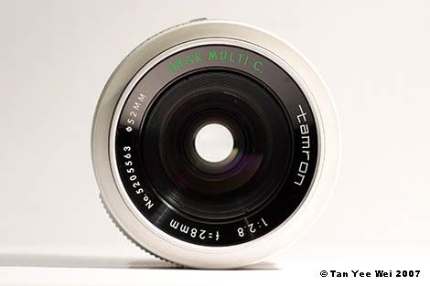
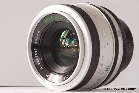
Yesterday, I acquired a new lens (yes I know, again). A Tamron 28mm f/2.8 on Pentax screw mount, which is very close to my Meyer-Optik Görlitz Lydith 30mm f/3.5 (2 mm wider, half a stop faster). Finished in brushed aluminium, the lens is quite a striking difference to all those black rubber-clad tubes out there.


Cyclops

Click here for large size image
Click here for Deviant Art entry


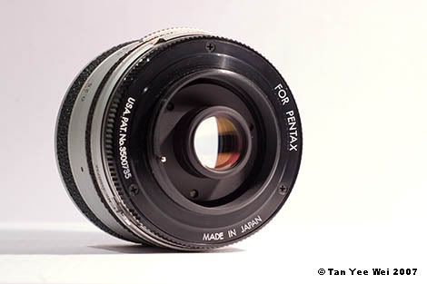
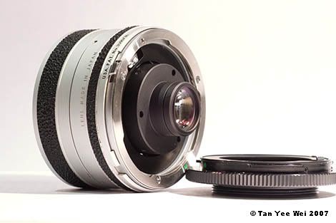
The shop did not know the mount for the lens, and it was generically labelled as “fits most SLR cameras”. It’s actually a Tamron Adaptall 2 system which can be adapted to fit Canon, Nikon, Pentax K, Minolta, Konica and M42 mounts. This particular specimen came with the M42 screw mount, but someone made a mess and thought it was a T-mount (like the M42, the T-mount has 42 mm screw threads but with different thread widths). And the secondary market for T-mount lenses is very small.

Hence, it was cheap.


Click here for large size image


So, I now have an arbitrage opportunity. Essentially, buy low sell high with no value adding.

Also, my position appears to be hedged by means of a put option (because I managed to get the salesperson to wrongly ‘confirm’ that the lens is a T-mount, I have a leeway in returning the thing if the need arises).

I didn’t know specialist knowledge can be so useful...


Click here for large size image
The rear of the lens showing the M42 mount


Click here for large size image
The workings of the Adaptall 2 mechanism with the Adaptall - M42 adapter removed


See my newly expanded vocabulary? I’ve been levelling up.

Labels: , ,

Saturday, July 28, 2007

Meyer-Optik Görlitz Lydith 30mm f/3.5

And later marketed as Pentacon 30mm f/3.5


Zebrlet
(Little Zebra)

Click here for large size image


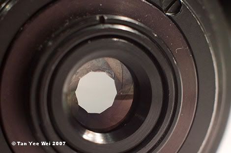
10 aperture blades for decagonal out of focus highlights


Click here for large size image
Simulation of Fuji NPH 400 using Alien Skin Exposure. Note the grain visible in the large image

Labels: ,

Tuesday, July 03, 2007

A brief histogram-based qualitative comparison between the Panasonic FZ-30 and entry-level DSLRs

Abstract
The objective of this investigation was to compare the dynamic range of the Panasonic FZ-30 with entry level DSLRs. Lens flare is also briefly discussed.


Introduction of concepts
In general, cameras are devices that record light brightness values in the form of a continuous bounded spectrum of dark (black) to light (white). On typical (film or digital) cameras, dark areas are rendered as black while light areas are rendered as white.

The black and white areas represent the limits of the sensor- the sensor cannot detect light levels less than the black areas, and light levels more than the white areas. The ratio between light levels required to produce black and white areas on the sensor is known as the dynamic range of the sensor.
Dynamic range explained

Dynamic range is typically quoted in units ‘stops’. One stop represent 2 times of difference in light intensity; two stops represent 4 times; three stops, 8 times; 4 stops 16 times; 5 stops 32 times…

At first glance, it may appear odd that the dynamic range is quoted in multiplicative form (8 times, or 3 stops) instead of additive (3 lux, 4 lux, 5 lux…). The logic is demonstrated in the following example:

A hypothetical sensor would be black if 5 photons or less hit it, and would be white if 160 or more photons hit it. Once can see that the dynamic range is 160/5 = 32 times, or in a more conventional notation, 5 stops.

Consider two light sources giving out 5 photons per second and 3200 photos per second. Exposing a sensor to each of these sources for a second would expose them to give black and white, as the sensors would receive a total of 5 and 3200 photons respectively in that one second of exposure.

However, let the light sources be brightened significantly, so that the dim light now throws out 5000 photons per second, and the bright light is worth 3,200,000 photons per second. Exposing the same sensors to these light sources for a short period of time, 1/1000 second, would still result in 5 and 3200 photons on each sensor, again giving us black and white.

In both cases, the ratio of light intensities between the bright and dark sources is the same:
3200 photons per second / 5 photon per second = 32
3.2 million photons per second / 5000 photon per second = 32

However, the difference in intensity is not identical:
3200 – 5 = 3195 photons per second
3195000 photons per second

Thus the multiplicative manner of describing dynamic range makes more sense than additive.


Description of Cameras

The Panasonic FZ-30 is a regarded as a prosumer point-and-shoot superzoom camera with a fixed lens (7.4-88.8 mm f/2.8-3.7) of Leica design.

Entry level DSLRs used were the Nikon D40 and Canon 300D, both using their respective kit lenses (both 18-55 mm f/3.5-5.6).


Methodlogy and results

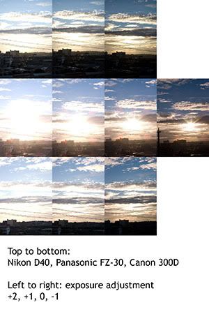
A scene with excessive highlights and shadows was captured at various exposure settings using all three cameras. The exposures were calibrated to be exactly the same: ISO 100, f/5.6 and exposure times of 1/200, 1/400, 1/800, 1/1600. In the case of the Nikon D40, it does not have the ISO 100 setting, so exposure times were halved to compensate for doubling the sensor’s sentivity.

The exposure corresponding to ISO 100, 1/800s and f/5.6 was arbitrarily chosen as the baseline exposure (0).


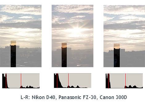
The captured images were cropped to contain approximately identical portions of the scene. The cropped scenes are presented in the figure below.


Click here for large size image


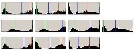
The histogram for each scene was observed in Photoshop CS2, and captured by using the Print Screen function. Distinct peaks (corresponding to large areas of similar darkness) were marked.
Histograms explained

Histograms show the frequency of various darkness levels within the image. The horizontal axis shows the darkness of pixels (dark on the left, bright on the right) and the vertical axis shows the quantity of pixels corresponding to each darkness level.


Click here for large size image


As the marked histograms show, the Panasonic FZ-30 has a remarkably narrow dynamic range. The main indicator is that where the DSLRs can accommodate 3 distinct peaks in the first two exposures, the FZ-30 is unable to do so even in the final one where the green peak is pushed closest to the left.

Curiously, the histograms from both DSLRs show that certain brighness levels are not represented (the histogram having zero height between the green and blue peaks) while the Panasonic one does not fall to zero.

Further investigation shows that this is due to lens flare. Internal reflections from the intense sunlight were not well controlled, resulting in light hitting the sensor where it should not.

A region of the scene was further cropped so that it contained a portion of the dark foreground and a bit of the bright sky. Ideally, the horizon should be a sharp division between the dark foreground and bright clouds. A histogram of this cropped region should have two sets of peaks- a dark one corresponding to the dark foreground, and a light one corresponding to the clouds.


Click here for large size image


The histogram from the Panasonic FZ-30 shows that some of the light from the sun has spread into the dark foreground, resulting in a gradual drop off in brightness instead of a sharp transition.


Summary of results
Compared to entry level DSLRs, The Panasonic FZ-30 has a sensor with comparatively low dynamic range and lens which suffers from noticeable flaring.


Concluding remarks
The results are not surprising.
The Panasonic FZ-30 has a very small sensor (approximately 7.4 mm across) while the DSLRs have much larger sensors (approximately 24 mm across). The resolution is of these sensors not remarkably different. The DSLRs’ larger sensors allows each pixel to have a larger area and collect more photons. As a result, large signal amplifications is not required, and noise is well controlled thus allowing usable data to be extracted from regions with low light.

The FZ-30’s 12x larege aperture (f/2.8 - 3.7) zoom lens requires more compromises in terms of various design objectives compared to the 3x zoom (f/3.5 - 5.6) on the DSLR kit lenses.

Overall, these are the inherent drawbacks of having a high resolution sensor and large zoom range on a relatively small camera body. The Panasonic FZ-30 serves as a general purpose camera which does many things (macro, wide, long telephoto) with a small, lightweight package. It lies in a different category and has a different target market from DSLRs.

Labels: , ,

Thursday, June 07, 2007

Extension tubes are fun

Photo concept blatantly stolen (without permission, but credit is being given now) from my brother.


Jupiter-9 80mm f/2.0 with extension tubes


Click here for large size image
Jupiter-9 80mm f/2.0 with extension tubes


That's a portion of the back of a chair.
Hanimex 400mm f/6.3 with extension tubes


Click here for large size image
Hanimex 400mm f/6.3 with extension tubes. Fuzzy optics was probably excarberated with shake from mirror slap

Labels: ,

Tuesday, June 05, 2007

Hello, world!

The Canon EOS 300D arrived in the mail today. Finally, my M42 manual focus babies lenses have a digital sensor to call home.


Click here for large size image


Click here for large size image


Naturally, these photos were not taken using the Canon kit lens.

Labels: ,

Sunday, June 03, 2007

Hanimex 400mm f/6.3


The Universe's Edge

Click here for large size image
Click here for Deviant Art entry


Due to the lack of anything better to do on a Sunday afternoon, I will write at length about my recently acquired lens.

Please close this window/tab if lenses do not tickle your fancy.


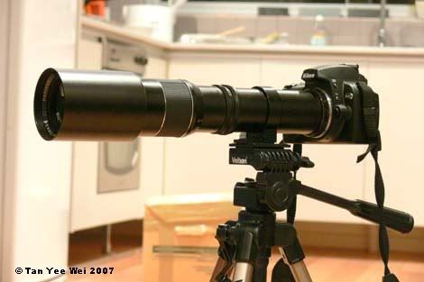
The Hanimex 400mm f/6.3 arrived on Friday, and it is a large tube of metal and glass.

With a tripod mount located mid span, preposterously long focal length and small optical sensor, this is one of the long-lens optical systems of my dreams. With an effective focal length of 600 mm on the Nikon D40 and 640 mm on the Canon 300D, this would give a horizontal viewing angle of approximately 3 degrees. The lens comes in a generic T-mount which can be adapted to various camera mounts.

The other optical system of my dreams is a camera mounted on a massive and ridiculously expensive reflector telescope on an equatorial mount and with appropriate solar filters.


Taken from 8 m away, this scene was one of the first photos shot on The Architect’s Nikon D40.


Click here for large size image


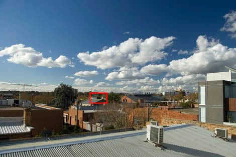
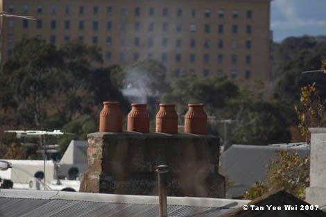
Outdoors, the lens’ narrow viewing angle became even more apparent.


Click here for large size image


The Nikon D40’s kit lens at 18 mm shows the difference between wide and tele. The area marked in red shows the region of the above image.


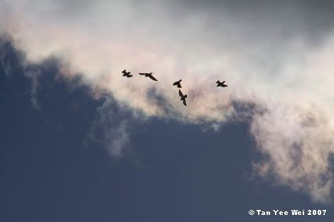
Despite the absurd length, tracking birds in the sky is not as difficult as initially assumed. They lens may be heavy, but the generous length offers plenty of holding places. Supporting it on the mass centre, it’s actually quite comfortable to track moving objects. Nonetheless, tracking is not easy.

This can probably be improved by devising a finder-scope of sorts on the side of the tube. Astronomical telescopes generally have a low powered, large viewing angle scope on the side to help determine where the telescope is pointed. This telephoto lens might benefit from a simple set of protrusions in line with the left eye for two-eyed tracking- left for locating, right for framing.


Sadly, this lens has its shortcomings. Apart from the obviously inadequate light collecting abilities, the glass also suffers from low contrast and general fuzziness. The rear optical element has a thin film of dust or other contaminants which needs to be cleaned soon.
In terms of light collection, the length means that shutter speeds need to be to the order of 1/400 s for photos to be shake-free. Compared with your typical standard prime lens (50mm f/2.0), the standard lens allows 90 times (6.5 stops) more light in.

For a total of AU$36.40, it is still a good buy despite the serious flaws. Where else can you get a 400 mm lens for 2 digits? A brand new Canon EF 400mm f/5.6L would cost AU$2,319 while the much faster 400mm f/2.8L IS USM would cost a frightful $13,709.
On a seperate note, the EF 1200mm f/5.6 L USM was made to order with a price tag of US$90,000.

Labels: ,